CAD for Mechanical Engineering, Rutgers University
Spring 2019
Skills
Computer: SOLIDWORKS
Leadership: Team Lead
Language: Technical Writing, Public Speaking
Team
Interdisciplinary Undergraduate Group of Six (Biomedical, Industrial, Materials Eng)
Project Summary
The Da Vinci Clock was recreated in the CAD for Mechanical Engineering course, alongside a team of interdisciplinary engineers. The clock offered an exemplary project for SOLIDWORKS modeling because of the numerous gears and the inherent necessity to maintain accuracy in gear size and ratio. In brief the clock contains numerous gear mates that allow for the clock to rotate at the correct ratio of speeds corresponding to minutes and hours. The case contains wheels that rotate and spin together as well as a door that without the lock opens and closes 180°. Finally the keys of the padlock spin and the lock bar opens and closes, limited by a distance mate.

The full clock, case, and lock assembly.
Background
Many of Leonardo Da Vinci’s drawings and writings of parachutes to botany are compiled into the 1199 page Codex Atlanticus, showcased at the Biblioteca Ambrosiana in Milan. Within the numerous creation lies a lesser known clock. Da Vinci was not the inventor of clocks, and in fact clocks had already increasingly becoming more accurate, however he offered improved mechanism for telling time. The clock he sketched contained two separate mechanism for hour and minutes and was powered by weights, gears, ropes. Although promising, this design was never pursued and there is currently little mention of this clock beyond its retail sale as a children’s engineering kit.
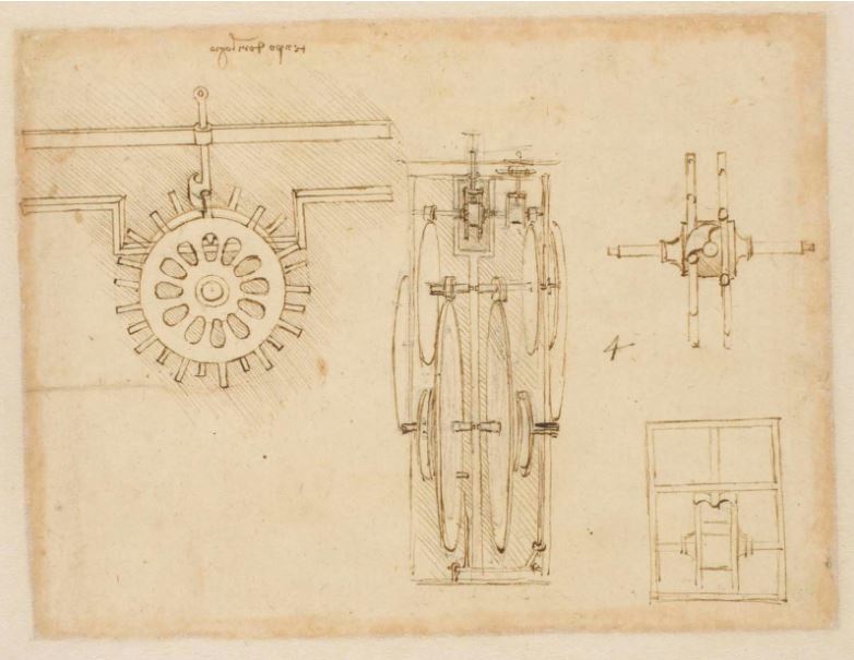
Page 964 of Codex Atlanticus sketching a clock mechanism taken from here.
Despite the paucity of historical information available, the Da Vinci Clock offers an exemplary project for SOLIDWORKS modeling. The numerous gears and the inherent necessity to maintain accuracy in gear size and ratio for a standing clock offered a challenge and opportunity to utilize the skills learnt in the classroom. Therefore, with this in mind, recreating the now commonly sold clock model was pursued as the final group project. Beyond the clock, a mobile case and lock were added to further challenge the group with different mechanism and mates, as well as add further flair to the submission. In total the project contains 63 unique parts, well beyond the 30 part requirement.
The project was built together as an interdisciplinary group of six members from five majors: aerospace, biomedical, industrial and systems, materials science, and mechanical engineering. Given the unique group, we wanted to deviate from the traditionally pursued mechanical projects such as weaponry or a transportation vehicle, so ultimately chose the clock model.
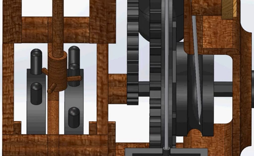
Oscillating motor shaft at the back of the clock driving gears during an animation.
My Role
I was the project lead and therefore oversaw the entire design, modeling, and assembly process. My specific roles included case/wheel part creation, assembly and engineering drawing, final full assembly, and final animation video.
The case was constructed from my own measurements and designs. The parts can be sectioned into glass panels, stainless steel hinges and lock holder, a mahogany base, and poly(methyl methacrylate) caster wheels. The case and glass panels are envisioned to be held together through adhesives to provide a seamless look. Inspirations for each component came from everyday objects and their dimensions.
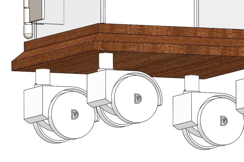
Caster wheels attached to the bottom of the case.

Top view of the case when open, highlighting angle limit mates and hinges.
Several considerations had to be made while making the case. For instance the swinging door could not phase through other parts of the case nor could the hinge parts with the top panel and itself. Evidence of post creation modifications to the model can be seen in the top panel which has an arc section cut away from the corner to open room for the top hinge pin. Another consideration was the placement of the outer lock holder and lower hinge. In both cases small ledges or divets in the parts were made to mark the proper location as to align the components. In the case of the outer lock holder, the wall and holder were both edited after creation to have midplanes for coincident mating.
The main mechanism for the case is the door opening and closing. The physical limits to this movement are the door not phasing through the other glass panels when closing or opening all the way and hinge components not overlapping when the door opens. To avoid these problems an angle limit mate was applied between the door and the panel attached to the lock holder’s rightplanes, both of which are parallel along the door when the case is closed. The angle range was 0° (door closed) to 180° (door opened). The top face of the door was also made coincident with the bottom face of the top glass panel to avoid any collisions and merging as the door closed.
Special consideration was also given to the wheel construction. In order to ensure that both wheels spin together, the pin that connected the two wheels contained a key extrusion that would insert into cuts in the wheel hole. A similar system was implemented between the pin that inserted into the case and the wheel holder. The wheels also mated for them to spin and rotate together to give a physical interpretation of when the case needed mechanical movement. While the key feature ensured that each wheel would spin with its counterpart, a gear mate with a 1 to 1 ratio were implemented between each wheel assembly to establish equal rotation when emulating how the wheels would spin when the case was pushed. Although another 1 to 1 gear mate could have been implemented between the pins that connected the wheels to the case, a parallel mate was made between the planes of the wheel casing so that each wheel would rotate together, again emulating how the wheels would turn in real life.

The final full assembly pictured in the Carnegie Museum of Art.
The full assembly was constructed by importing each subassembly for the clock, case, and lock into a new assembly file and dissolving all subassemblies. The origin of the case base was mated with the global origin and the planes were aligned to avoid any movement. The bottom face of the clock’s base was mated coincident with the top face of the case base. Limit distance mates were then placed between the case’s back panel face and the corresponding parallel case base plane, as well as between the case side panel’s face and its corresponding parallel clock base face, to restrict the clock’s movement to within the closed case (touching the side and back walls and the door when in the completely closed position). The lock offered a challenge to position since there is no gravity in the Model tab, meaning it would not naturally rest on the edges of the lock holes. To solve this issue tangent relations were placed between the lock shackle and both lock holes’ outer edges when the door was in its completely closed position. An angle limit mate was also placed between the lock shackle’s vertical plane parallel to the closed door and the global plane parallel to it, from 0° (hanging downward) and 180° (hanging upside down).
Exploded disassembly of the case and wheel subassemblies.

Animation of the oscillatory portion of the clock, creating the illusion of the passing of time.
The animation video of the model was complex to make, being constructed from several different videos. Because of the numerous parts and mates, SOLIDWORKS would repeatedly crash when attempting to export a single video. Therefore small videos of the full assembly and larger videos of the individual subassemblies were spliced together to create a final animation. Overall the animation introduces and highlights the complexities of each major part of the projects: clock, case, and lock, including the synchronised harmonic motion of the T-bar versus the constant gear motion without parts phasing.